NEW ! IMDI
Version
2.0 released. The new release of IMDI includes
support for the new E2V CCD
at LRS/Dolores and the new
set of grisms. In addition, some known issues in previous
versions
have been fixed.
Getting the IMDI
software:
1)
Request
the most recent version of the IMDI package to the
TNG
resident astronomer; be sure
that
the IDL
Astronomy User's
Library is
installed in your system and included in the IDL_PATH.
2)
Unpack the IMDI tarball in your working directory.
3)
Create a file "mos.dat" appropriate for your
version of IDL. For example,
cp mos_60.dat mos.dat to
run
IMDI under IDL versions 6.x. Use
mos_54.dat for IDL versions 5.x.
4) Run the setup file: csh
chooseCCD E/L
where E is the flag to be used if
the preimaging was taken with the new E2V CCD, and L is used for
images taken with the old LORAL CCD.
5)
To run IMDI, start IDL and type the following commands (the first one
is needed to correctly display the image on a 24-bit screen):
device, decomposed=0
@ mos
Note for Linux Users. There are two
known issues when using IMDI with Linux X-window systems. The first is
that the
IMDI display is not
restored (i.e. it remains black) when windows overlap. Second problem,
changes in the IDL color table are not supported with the 16/24-bit graphics that
is the default in Linux. As the results,
the color controls enabled by the COLOR button do not take immediate
effect on the displayed image. Both problems will be fixed in the
next version IMDI V.2.1. In the meantime, we suggest the following
workarounds. 1) Edit the X-windows parameter
file
(e.g., /etc/X11/xorg.conf) by adding the Option "BackingStore" (and the
"Virtual" option if you run IMDI on a small-screen laptop) as in this
example.
2)
Load your image, experiment a bit with [COLOR] to find the best table
(although the default MOS table will do in most cases), then
re-[LOAD] the image. The new color table will remain in
effect until you quit IDL. This feature works on Linux only with IDL
6.x. It is convenient to do that before
starting any mask design.
Using
IMDI.
Using the IMDI is intended to be self-explaining. Run it by typing "@
mos"
from IDL (Vers. 5.4 or later).
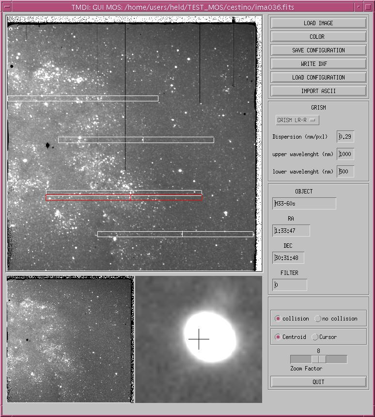
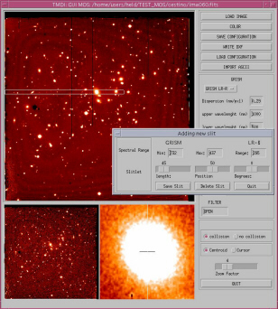
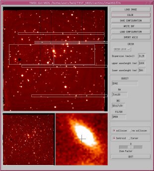
Images
taken with the DOLoRes are displayed on a 3-window
screen,
from which targets are interactively picked up and centered. Slits are
adjusted under control of a real-time anti-overlap algorithm. |
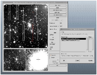
Opening a pre-imaging FITS file
using  is the
first step. The program can read both ".fits"
and ".fts" image files. The upper window (``main window'') of the
Interface
is used for image selection, while the lower rigth window (``zoom
window'') is used for fine centering of the targets. The lower-left
section gives an overview of the field (currently unused). The color
look-up table of the
image can be modified using is the
first step. The program can read both ".fits"
and ".fts" image files. The upper window (``main window'') of the
Interface
is used for image selection, while the lower rigth window (``zoom
window'') is used for fine centering of the targets. The lower-left
section gives an overview of the field (currently unused). The color
look-up table of the
image can be modified using 
Note, however, that MOS is
the recommended lookup table (also VOLCANO was
found to be useful in case of very faint targets).
|
|
|
|
When IMDI is started, the basic setup
information (CCD, grism table, etc ...) are read from a TNG/DOLoRes
setup file provided with the release of the mask design software. Just choose
your grism from the menu. The spectral range can be edited
by changing the upper and lower wavelength in the small windows (you
must hit the RETURN key in each field, due to a known
limitation of IDL). |
Note.
You may notice that the default wavelength ranges for the grisms are
different from those listed in the DOLoRes documents. This is not a
mistake. While
the latter are effective ranges determined by the size of the CCD in
the
case of a central (long)slit, the default grism ranges for the MOS are
related to the wavelength range covered by the grisms.
|
|
Some data on the target field are read from the FITS header
and displayed in the middle part of the main panel. This information
will be inherited
by the mask files and transferred to the associated documentation. |
|
Objects are selected by clicking once (left button of the mouse) on the main
window. Then click on the zoom window with the right button to center the target. The size of
the box can be changed by using the middle button.
Before that, choose the
appropriate centering method  in the main panel. Rectangles are used to outline the
location of the spectra. These are computed using information in
the IMDI instrument database and
the image header. The slits are interactively adjusted by the user
under
control of an anti-overlap algorithm. in the main panel. Rectangles are used to outline the
location of the spectra. These are computed using information in
the IMDI instrument database and
the image header. The slits are interactively adjusted by the user
under
control of an anti-overlap algorithm.
NOTE. Using "centroid", the slit appears mis-centered in
the zoom window. This problem only affects the graphics, not the
computed centroids, and should be ignored.
|
The [import ascii]
function allows importing of a list of targets from an ASCII catalog
produced by automated image analysis and classification programs (e.g.,
Sextractor)
or by hand. The first three columns must be IDENTIFIER, x_pixel,
y_pixel. Any further columns are ignored.
|
Clicking on a target activates the
Slit
Control Panel. By this mechanism, you can either choose a new
target
or pick up and modify a previously defined target. The length, setting,
and angle of the slitlet are defined by sliders in a
self-explaining
way. The minimum length of slits is 8 pixels (2"), even if you specify
0.
After interactive editing, save the slit, delete it, or just quit
without
changes. The buttons  and and  in the main panel allow you to suspend mask editing at
any time and resume it later. The
"saved configuration" is a
temporary IDL structure not to be confused with the final
output
of the mask design. in the main panel allow you to suspend mask editing at
any time and resume it later. The
"saved configuration" is a
temporary IDL structure not to be confused with the final
output
of the mask design.
|
|
The IMDI anti-collision algorithm warns you in real time
about spectrum overlap by highlighting the overlapping spectra. Our
advice is not to pack the spectra too close to each other, letting some
extra space between spectra. This will make reduction much easier
!
Still, the final decision
about accepting these warnings is left to user's responsibility,
although there are software checks against slitlets violating severe
mechanical constraints. In particular, slits
too close to the edges are rejected
by safety checks. An automatic slit optimizer is not
foreseen
with the first release of IMDI.
|
|
|
|
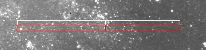
A useful feature allowed by the mask
design software (and by Mask-Mode MOS observations) is stacking of two
rows of spectra. Using a low-dispersion grism in combination with an
appropriate filter to reduce the spectrum length, more than one
spectrum can be aligned along the dispersion direction. (Note, however,
that this mode is not offered
as a standard facility of
DOLoRes.) A multiplex factor of 2 will allow up to 80-100 spectra
per mask (10" slits). |
Reference stars.
At least two reference stars, well spaced
across
the dispersion direction, must be included in each mask. The
presence
of the reference holes (in practice, slits with minimal length) is
required
to speed up MOS pointing at the telescope. Of course, the two stars
must be on
the
same coordinate system as the targets.
|