- Science objectives
- Mask - Mode MOS vs. Multislit Assembly
- The control computer and software
- The milling machine
- Mask cutting and processing
- The masks: quality checks
- Operation flow
- Pre-commissioning tests at Cima Ekar
- MOS commissioning at the TNG
Multiobject
Spectroscopy
at the
Telescopio Nazionale Galileo
| Overview and project team | |
| Scientific case | |
|
|
| Mask design | |
| Mask manufacturing | |
|
|
| MOS observations | |
|
|
| Documents |
![]()
The Mask-Mode multiobject spectroscopy (MM-MOS) at the Galileo National Telescope is an extended MOS capability complementary to the real-time built-in multislit assembly of the Low Resolution Spectrograph DOLoReS. The Mask-MOS facility represents a highly flexible tool for multiobject spectroscopy, with quality standards comparable to that of MOS facilities presently available at 4m class telescopes, at a very affordable cost (£ 40000 Euro) and with reasonable equipment size.
![]()
Scientific motivations for an extended MOS mode
Science objectives
In the VLT era, very deep cosmological surveys will be conducted at 10m class telescopes using large-field spectrographs (e.g., VIMOS). Still, multiobject spectroscopy at 4m class telescopes still offers a good alternative for less extreme targets in fields with size of the order 10', such as:
Mask - Mode MOS vs. Multislit Assembly.
The multislit assembly provided with the Low Resolution Spectrograph DOLoRes (19 slits with fixed length of 20 arcsec) will be the standard option for most programs. It has several practical advantages, first of all a remotely controlled slit setup, possibly during the observing night, and optimal quality of the slitlets.
However, there remain a number of scientific cases where the uniform and fixed (along the spatial axis) coverage by the multislit assembly seriously affects observation efficiency. On this basis, an extended MOS mode was proposed by members of the Instrument Definition Team of DOLoRes (Held, Ramella & Cristiani 1995). A similar concept was also adopted for MXU at ESO.
In the Mask-Mode MOS (MM-MOS),
the targets
will be observed through multislit masks prepared for each
target
field using a mask manufacturing facility locally available at
the
TNG. The main advantage of this mode is its flexibility: mask can
include
a large number of slits with arbitrary position, orientation and
shape,
with very little constraints aside from those needed to prevent
spectrum
overlap. Obviously, masks also have some drawbacks: they must be prepared
in advance of the observing night, requiring specialized staff and careful
processing.
![]()
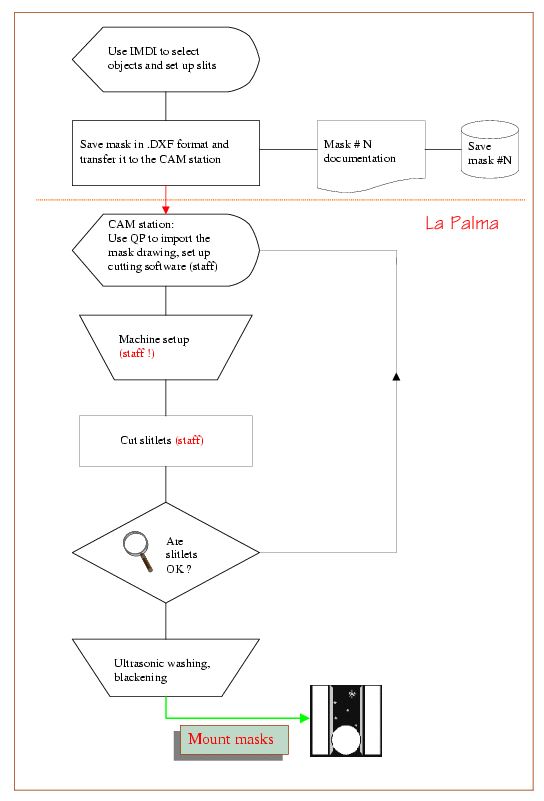
The following flow chart
summarizes the mask design and manufacturing process outlined in the
following sections.
 |
| Using the Interactive Mask Design Interface. The rectangles represent the location of the spectra, calculated from the instrument database. Most operations are executed using cursors, buttons and sliders in a self-explaining sequence. Instructions here. | 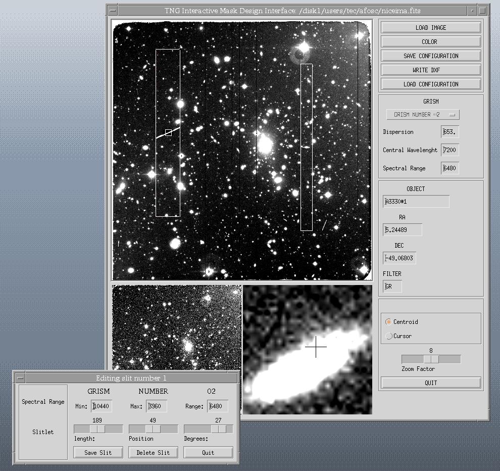 |
Some features of IMDI:
The control computer and
software
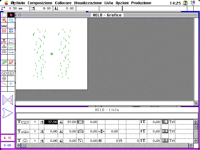 |
A dedicated PowerPC computer, equipped with a network interface card and TCP/IP communication software, controls the cutting machine via the Quick Plate (QP) Software. The drawing files produced by the astronomer are converted into low-level instructions used to drive the milling machine. |
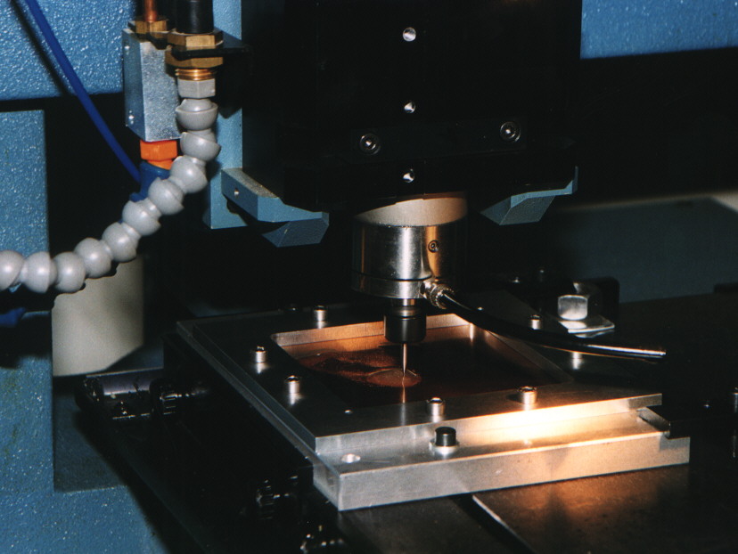
The milling machine
 |
|||
| A general view of the mask manufacturing facility. All the electronic components and the control computer are conveniently arranged in a dedicated rack close to the CNC machine. Mask production is managed by TNG staff only. | 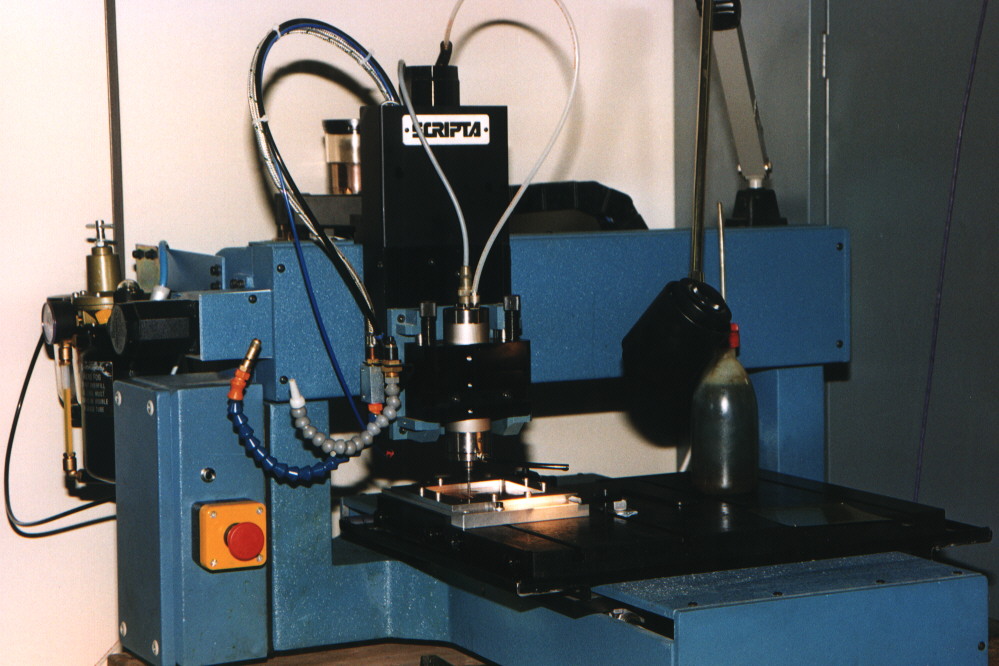 |
||
Mask cutting and processing
 |
A detail of the machine head cutting a mask during our tests of different materials and tools. | ||
| An example of a test multislit mask where several slits were cut using two different tools (200 and 300 m m in diameter). This plate was made out of a 0.2 mm thick bronze sheet. After cutting, the masks are effectively cleaned by ultrasonic washing. Two reference holes ensure accurate repositioning of the mask in the plate holder. A third pinhole made during mask cutting (not shown here) will ensure correct mounting. | 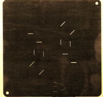 |
||
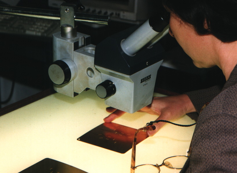
The masks: quality checks
| Checking the quality of the slitlets is an important step of mask production. After inspection at the microscope, the plates are painted with an antireflection coating, mounted on the holding frames, and kept in a dust-free area until the frames are mounted in the slide assembly of DOLoRes. |
|
|
 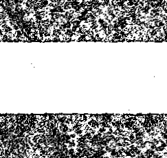 |
This figure shows a microphotograph of a 200 m m slitlet after ultrasonic cleaning. The enhanced contrast image allows assessing the degree of micro-roughness of the slit edges. Both the r.m.s of the slit edges and their parallelism over a 20'' length are better than 3 m m. | |
| Positioning accuracy of the slit centers | ± 10m m or ± 0.06" |
| Parallelism of the slit edges over a slit length of 20 arcsec | ± 3 m m |
| Minimum slit width on the focal plane | 200 m m or 1.1" |
| Micro-roughness of the slit edges | ± 3 m m (rms) |
These characteristics basically
meet the specifications, except for the minimum slit width that is
constrained by the size of micro-mills available on the market.
![]()
Operation flow
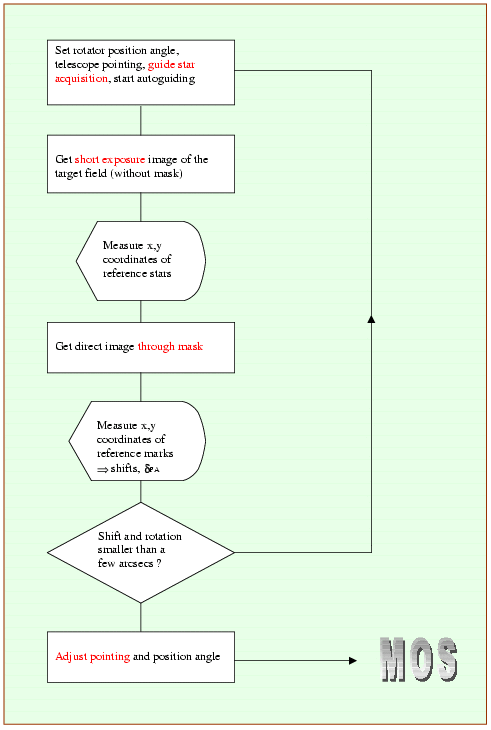 |
This flow chart outlines the
telescope pointing and target acquisition procedures, once the masks
have been mounted in the DOLoRes slide assembly. The adopted procedure
assumes that the masks can be repositioned on the optical beam with
high accuracy (i.e. 5 m m or better). The pointing sequence is guided by a MOS
Pointing User Interface developed during the pre-commissioning tests.
Pre-commissioning tests
| The mask design software and the pointing procedures were pre-commissioned in advance of th efirst light of TNG using the 1.8m telescope at Asiago Cima Ekar. The imaging low-resolution spectrograph AFOSC was employed as a working model of DOLoRes. MOS spectra of galaxies in three nearby Abell clusters have been obtained on the night of Jan. 11, 2000 using a scaled version of the masks for TNG. |
 |
![]()
The following documents are available for download as gzipped postscript files:
![]()
 Questions,
comments and suggestions are welcome.
Questions,
comments and suggestions are welcome.